
Bottom Extra Bar Length in Beam: L/3 Formula Explained
how to calculate the bottom extra bar and top extra bar length in a beam using the practical L/3 formula, with two solved examples and correct placement zones as per IS 456 guidelines.
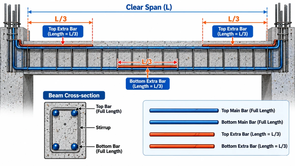
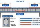
The bottom extra bar length in a beam is generally taken as L/3 of the clear span, added at the center of the beam alongside the main bottom bar to resist positive (sagging) moment with development length (Ld) added separately at both ends.
If you’re new to reading a Bar Bending Schedule (BBS), the term “extra bar” can feel confusing, since both the top and bottom reinforcement have their own “extra” bars serving different purposes. This article breaks down both, with real numbers.
What Is an “Extra Bar” in a Beam ?
A beam carries two main reinforcements the top bar and the bottom bar running continuously across the full span. But in certain zones, the bending moment becomes high enough that the main bars alone aren’t sufficient. In those specific zones, an additional bar is added, called the extra bar.
There are two types
- Top extra bar placed near the support (column junction), where negative (hogging) moment is highest.
- Bottom extra bar placed at the center of the mid-span, where positive (sagging) moment peaks.
In simple terms: wherever the beam is trying to bend the most, extra steel is added there to resist that bending.
Bottom Extra Bar Length Formula
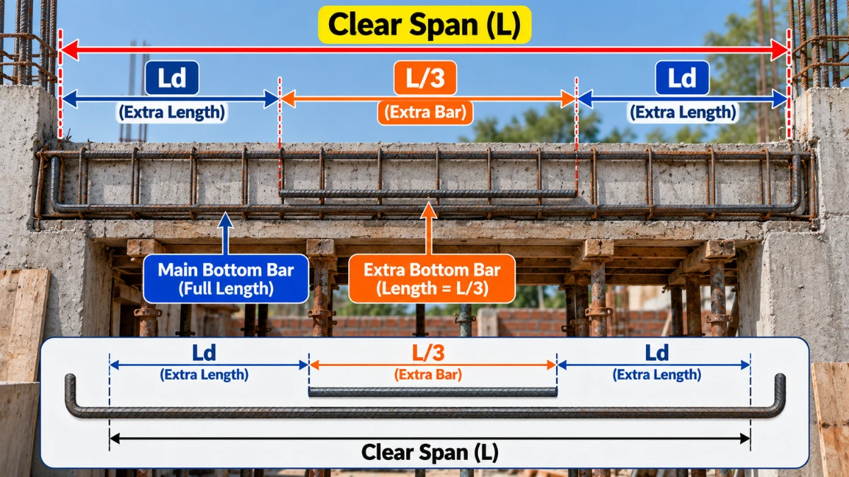
The practical site formula is:
Bottom Extra Bar Length = (L/3) + 2 × Ld
Where:
- L = clear span of the beam
- L/3 = the portion the bar extends across, centered symmetrically at mid-span
- Ld = development length (anchorage), added at both ends so the bar bonds properly with the surrounding concrete
This formula is based on the development length concept from IS 456:2000, where Ld depends on bar diameter and the grade of steel/concrete (usually between 40d and 50d always confirm the exact value from the structural design).
Worked Example 1 Bottom Extra Bar
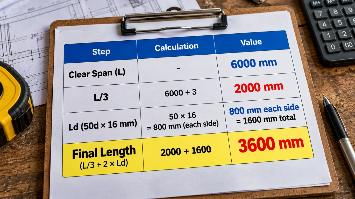
Assume a beam with clear span L = 6000 mm, using a 16 mm dia bottom extra bar, with Ld taken as 50d.
Step 1 Calculate L/3:
6000 / 3 = 2000 mm
Step 2 Calculate Ld (for 16 mm bar, 50d):
50 × 16 = 800 mm per side, so 2 × 800 = 1600 mm total
Step 3 Total length:
2000 + 1600 = 3600 mm (3.6 metres)
So this 16mm bottom extra bar would be cut to 3.6 metres and fixed at the center.
Top Extra Bar Length Formula (For Comparison)
The top extra bar follows the same logic only the location differs. It goes near the support, not at mid-span.
Top Extra Bar Length = (L/3) + 2 × Ld (measured from the support face though some drawings use L/4 instead; see the comparison table below)
Worked Example 2 Top Extra Bar (A Different Real Scenario)
Now apply the same formula to the support region of a continuous beam, keeping the same clear span L = 6000 mm, but using a 12 mm dia bar (top extra bars are often a smaller diameter than bottom ones).
Step 1 L/3:
6000 / 3 = 2000 mm
Step 2 Ld (50d for 12mm):
50 × 12 = 600 mm per side, so 1200 mm total
Step 3 Total length:
2000 + 1200 = 3200 mm (3.2 metres)
Same formula, different diameter and location, different final length. This is exactly why checking the bar mark’s diameter on site matters otherwise the quantity comes out wrong.
L/3 vs L/4 vs L/5 Which Convention Applies When ?
On site, you’ll come across L/3, L/4, and L/5 conventions because this depends on the actual structural drawing/design, not one universal fixed rule. Here’s how they typically differ:
| Convention | When It’s Used | Typical Beam Type |
|---|---|---|
| L/3 | The most common thumb rule, used for both top and bottom extra bars in simply supported beams | Residential simply supported beams |
| L/4 | When the structural drawing takes a more conservative moment distribution | Medium-span RCC framed structures |
| L/5 | At interior supports of continuous beams, where moment reversal is more critical | Multi-span continuous beams |
Important: These are all practical thumb-rule conventions in common use, but the final authority is always the structural design drawing. Never work off assumptions on site always follow the structural engineer’s drawing.
Where to Place the Bottom Extra Bar (Per IS 456)
The lapping/curtailment zone for bottom bars matters too. As per IS 456:2000 guidelines, the lap or curtailment of bottom bars should be at the column junction or at an L/4 distance from the column face never in the mid-span, since that’s a tension zone and lapping/curtailing there would be structurally unsafe.
Keep in mind the extra bar concept is different from curtailment or lapping. An extra bar is added (for extra strength), while curtailment/lapping is about joining or reducing an already installed bar. Don’t confuse the two.
Common Mistakes Beginners Make
- Swapping the top and bottom extra bar locations top extra goes near the support, bottom extra at the center, not the other way around.
- Forgetting to add Ld taking only L/3 and skipping the development length at both ends, which results in a bar cut too short, causing rework on site.
- Applying the same formula to every beam the convention for a continuous beam can differ from a simply supported beam; always check the structural drawing.
- Mixing up diameters as shown in the examples, different diameters give different Ld values, so note the diameter of each bar mark carefully.
Quick Recap
- Bottom extra bar = at mid-span, to resist positive moment
- Top extra bar = near the support, to resist negative moment
- Formula: L/3 (or L/4, L/5 depending on the drawing) + 2 × Ld
- Development length depends on bar diameter and grade
- Always confirm from the structural drawing the thumb rule is only for estimation
If you want to quickly calculate your own beam steel requirement, try our Bar Bending Schedule Calculator and Development Length Calculator both apply this formula automatically.
Check Our Tool Bar Bending Schedule (BBS) Generator
Also Read Density of Cement 1440 kg/m³ Explained
Frequently Asked Questions

Ar. Prince Badaik Is A Civil Engineering And Construction Content Creator At Civil Cost. He Shares Practical Information About Construction, Building Materials, Quantity Estimation, Costing, And Structural Engineering In A Simple And Easy To Understand Way.




Comments (0)